Significance
Carbon fiber reinforced polymer structures are increasingly used in aircraft where mechanical performance, electrical current flow, and heat generation must be considered as connected design issues. This creates a demanding design problem because carbon fiber composites are neither simple insulators nor simple metallic conductors. Their electrical response depends on fiber orientation, yarn continuity, contact between conductive elements, polymer-rich regions, and the way current is introduced into the structure. When an electrical fault occurs, the current may pass through the composite itself before reaching ground, and the resulting Joule heating can become a local thermal issue rather than a purely electrical one. The problem is harder in three-dimensional woven composites. Unlike conventional laminates, 3D woven structures contain interlaced yarn systems that connect the material through thickness and across the plane in different ways. These architectures are attractive for structural applications because their yarn topology can improve damage tolerance and shape formability, but the same topology also creates a more complicated network for current conduction. A current injected at one local point does not simply follow a single fiber direction. It can move through yarn contacts, redistribute through adjacent yarns, and generate heat at locations that are controlled by both electrical resistance and thermal transport.
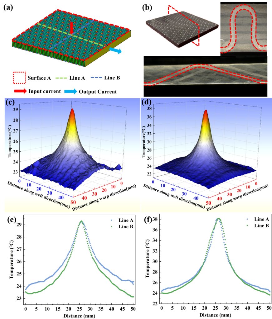
In a recent research paper published in Composite Structures, Dr. Xiaoyu Li, Dr. Juan Fang, Professor Bohong Gu, and Professor Baozhong Sun from the Donghua University developed an integrated experimental and finite element method for analyzing fault-current conduction and temperature distribution in 3D carbon fiber woven composites. They fabricated 3D orthogonal and angle-interlock woven composite specimens, measured relevant yarn-interface conductivities, and built microstructure-based electro-thermal models that represented yarn contacts directly. This made it possible to connect the measured response to specific yarn contacts and heat-transfer routes. The researchers produced both from carbon fiber tows and epoxy resin, then prepared as square specimens with exposed conductive surfaces and controlled electrical contacts. The fault-current condition was modeled as a local current injection at the center of the top surface, with current flowing toward a grounded side surface. This configuration was important because it better reflects the kind of localized electrical contact that may occur when a damaged or chafed cable touches a composite structure, rather than assuming current injection uniformly from specimen ends.
Electrical resistance and infrared temperature measurements provided the experimental basis, while microstructure-based finite element models were used to examine potential, current density, heat generation, and temperature evolution inside the material. The models represented the yarn systems, resin, copper electrode, yarn-to-yarn contact conductivities, and thermal boundary conditions. A useful feature of the study is that the interface conductivities were not treated as arbitrary fitting parameters. The researchers measured the conductivities of the relevant yarn contact combinations by replacing non-target yarns with glass fiber tows, leaving selected carbon fiber contacts for direct characterization. That design choice linked the simulated electro-thermal response to actual interface behavior rather than to an idealized homogeneous conductor.
The resistance was highest under the 45° electric field direction, particularly in the angle-interlock architecture. Temperature followed the same directional sensitivity: The peak temperature also occurred under the 45° direction, with the angle-interlock structure showing the stronger thermal rise. The investigators found at 45°, current transfer from the injected yarn to nearby yarns becomes more restricted, so the current density becomes more concentrated. At 0° and 90°, more conductive pathways are available, allowing current to spread through adjacent yarn contacts with less concentration.
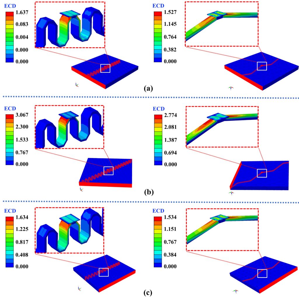
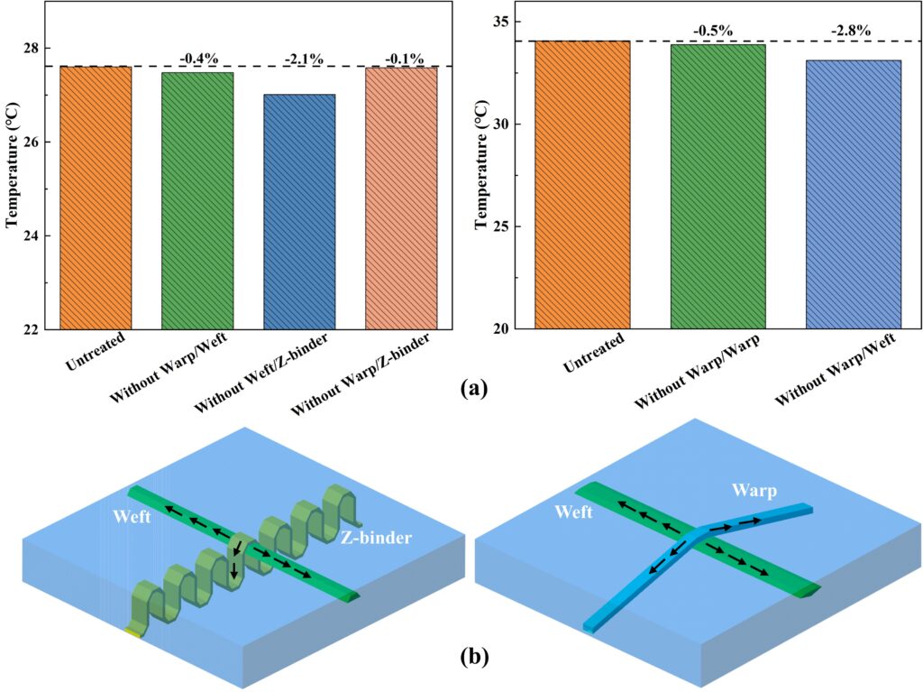
The team conducted numerical analysis and found when yarn interface contacts were included, current could leave the injected yarn and pass through the contact network into surrounding yarns. When those contacts were removed in the model, the potential and current-density fields changed substantially, with much higher potentials in the injected yarn. This comparison showed that even when a continuous yarn path exists, the internal contact network still plays a decisive role in distributing fault current. For the orthogonal woven composite, the weft/Z-binder interface carried the largest electrical contribution because the injected current entered through the Z-binder yarn and transferred mainly into the weft yarns. In the angle-interlock composite, the corresponding dominant interface was the warp/weft contact. Afterward, the authors studied the thermal response and noticed the highest temperature appeared near the injection location, where current density and contact resistance were concentrated. Heat then propagated through the current-injected yarn and into weft yarns through contact interfaces. Through-thickness temperature decreased with depth, while the in-plane thermal pattern evolved over time. In the orthogonal structure, heat transfer developed from the Z-binder into nearby weft yarns, producing a transition in field morphology during heating. In the angle-interlock structure, the different relationship between warp and weft transmission distances led to a different early-stage pattern.
The findings of Professor Baozhong Sun and colleagues have direct relevance to the design of composite aircraft structures that must operate close to embedded electrical systems, grounding networks, or current-return pathways. Under fault conditions, a damaged or exposed cable may inject current locally into the composite, and the resulting current path will depend strongly on the internal woven architecture. The work by Dr. Xiaoyu Li, Dr. Juan Fang, Professor Bohong Gu, and Professor Baozhong Sun provides a practical basis for predicting where current will flow and where heat will concentrate in 3D carbon fiber woven composites.
One important application is in the design of safer integrated electrical power systems in composite airframes. The study shows that yarn-to-yarn contacts, especially the interfaces between the current-injected yarn and weft yarns, strongly influence fault-current conduction. This means that engineers can use woven architecture and interface conductivity as design variables rather than treating the composite as a passive structural material. In regions where electrical cables, grounding points, sensors, or power electronics are embedded near carbon fiber components, the orientation of the woven structure and the location of likely contact points could be selected to reduce current concentration and avoid localized heating. The research work are also useful for thermal safety assessment and the researchers showed that the highest temperatures form near the current injection site, but the final temperature field is shaped by heat conduction through yarn networks, particularly the weft yarns. This can help engineers identify critical hot-spot locations in 3D woven composite panels and improve placement of grounding electrodes, insulation layers, or local protective materials. Since the 45° direction produced higher resistance and higher peak temperature, component designers may need to pay special attention to off-axis current paths rather than only testing along the principal yarn directions. Another application is in finite element-based certification and design screening. The microstructure-based modeling approach can be used to simulate fault-current response before full-scale testing, allowing engineers to compare woven architectures, interface conductivities, contact resistances, and current injection scenarios. This is especially valuable for aircraft components where destructive electrical fault testing is expensive or difficult to repeat. It is noteworthy to mention, the study supports the development of multifunctional composite structures in which mechanical performance, electrical conduction, and thermal response are considered together. The engineering value is clear: fault-current behavior in 3D woven composites can be traced to specific yarn paths, contact interfaces, and heat-transfer routes that engineers can measure, model, and refine during design.
Reference
Xiaoyu Li, Juan Fang, Bohong Gu, Baozhong Sun, Electrical current conduction and temperature distribution of 3D carbon fiber woven composites under fault currents, Composite Structures, Volume 373, 2025, 119697,
Go to Composite Structures